In this blog we are describing one of the very common topologies of Float Chargers used as a backup DC system in the large switch-gear installations.
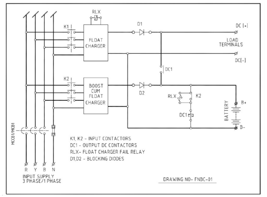
Block diagram of Float Charger and Float-cum- Boost Battery Charger
In this topology the float charger feeds load and trickle charges the battery through DC contactor contact DC1. Please note that DC contactor is always energized by battery bank. Float rectifier operates in constant voltage mode and maintains a constant voltage across the load terminal (settable between 2.0 and 2.3 V / cell).
During power outage the battery feeds load through the same path (closed DC1) and maintains uninterrupted supply at DC output terminal.
Normally the boost charger (or boost cum float charger) remains OFF. If battery voltage goes down after heavy discharge, then boost charger contactor K2 is switched ON by battery under voltage sensing relay and boost charger charges battery in constant current/voltage mode.
When boost charger is switched ON by K2, DC contactor DC1 is de-energised by K2 interlock thus eliminating the possibility of appearance of high DC voltage of battery (when charged beyond 2.3 V / cell) across the sensitive load
Now the float rectifier feeds the load in constant voltage mode and the boost charger charges the battery. At this stage if power fails, the battery feeds the load as soon as the DC contactor picks up. But total no break supply is maintained at the load through a tap cell diode, connected at 80% cell of the battery bank.
Battery voltage increases with charge and when it reaches a preset level, the battery over voltage relay is activated, which consequently switches OFF K2. The system goes back to normal mode of operation, that is, the float rectifier feeds the load and trickle charges the battery while the boost rectifier remains OFF.
Boost charger can also be switched ON manually for initial and equalizing charging.
In the event of failure of float charger, Float charger fail relay RLX is energized and switches ON Float-cum-Boost Battery Charger in float mode (that is in CV mode). DC1 is also energized so that the boost charger charges the battery and feeds the load. Float charger fail alarm is activated for service of the float rectifier.
ESI uses 3 types of AC-DC Converters in FC and FC-cum-BC Topology
- Three Phase 6 Pulse Thyristor Converter
- Single-Phase Half-Controlled Thyristor Converter
- Two Switch Forward Converter in SMPS
Electro Service India’s “Float and Float-cum- Boost Battery Charger” stands as a testament to the company’s dedication to Quality. Electro Service India plays a crucial role in providing DC backup system to major HT installations across PAN India and neighbouring countries.